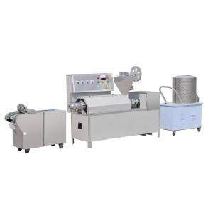
Detailed technical scheme of bean hull machine (Part 1)
Bean skin is a kind of nutritious food containing more protein, which is deeply loved by people.
Existing soybean hull processing generally adopts manual processing, which has low production efficiency and poor sanitation. There have also appeared soybean hull machines in succession, replacing manual production, which reduces the labor intensity of workers and greatly improves work efficiency.
This machine is a flat-rotor type. The radius of the inner and outer rings is different. The length of the bean strips is different. The difference is large. It is difficult to collect and is not convenient for mass production.
Technical realization elements:
The technical problem to be solved by the bean skin machine is that the bean skin strips mentioned in the background art are different in length, have a large difference, are difficult to collect, and are not convenient for mass production.
To solve the above problems, the technical solutions adopted are:
Structure: including frame components, rollers, hopper components, heating components, outer insulation cover and inner insulation cover,
The drum is horizontally arranged on the rack assembly, the hopper assembly is vertically arranged on the rack assembly, the heating assembly is arranged on the inside of the drum, the outer insulation cover is sleeved on the outside of the drum and fixed on the rack assembly, the inner insulation cover is arranged on the inside of the drum Fixed on the rack assembly;
The frame components of bean hull machine include front vertical plate, rear vertical plate, drive motor, scraper, discharge roller and cleaning roller.
The front vertical plate and the rear vertical plate are arranged symmetrically and vertically. The front vertical plate and the rear vertical plate include a horizontal plate placed horizontally, a vertical plate arranged vertically on the vertical plate, and symmetrically arranged on both sides of the lower part of the vertical plate The inclined plate of the two inclined plates is inclined downward, and the horizontal plate is convexly extended horizontally at the upper and middle of the vertical plate;
Two connecting rods are provided between the two first vertical plates of the front vertical plate and the rear vertical plate. They are fixed on the other ends of the two one vertical plates respectively; rollers are respectively provided on the four ends of the two connecting rods, and the two rollers on each connecting rod are located on the front vertical plate and the rear vertical plate;
Tie rods are respectively arranged between the two slant plates of the four sloping plates on the front upright plate and the rear upright plate. The ends are respectively set on the other two inclined plates through rotating parts;


